Best Books to Learn Mechatronics, in Order
Mechatronics is not a subject so much as an integration discipline: it asks you to be competent in mechanical design, analogue and digital electronics, sensing, embedded programming and control theory at once, and then to reason about the whole system. This path follows that structure. It starts with the two standard survey courses that map the territory, then builds the electronics and the sensing and actuation layers separately, then embedded control, and finishes with project-driven design books that put it all back together. A reader with an existing background in one of the pillars can skip that stage; a reader with none should expect this to be the work of a year, not a month.
The standard first course
BeginnerSee the whole territory once — sensors, signal conditioning, actuators, microcontrollers, system models — so that the specialised stages that follow have somewhere to attach.
▸ Study plan for this stage
Pace: Two to three months for the pair. Bolton's Mechatronics is 574 pages and reads quickly — a chapter a sitting is comfortable — and Alciatore and Histand's Introduction to Mechatronics and Measurement Systems is 544 pages that read considerably slower because they carry derivations. Read Bolton first
- Mechatronics as a chain rather than a discipline: physical quantity to sensor to signal conditioning to conversion to processor to actuator drive to mechanism, with the whole loop closed by measurement. Bolton's book is organised along exactly this chain and it is worth adopting the structure as you
- Signal conditioning as the part beginners skip and practitioners spend their time on: amplification, filtering, level shifting, isolation, and the impedance mismatches between a sensor and whatever reads it.
- Analogue-to-digital and digital-to-analogue conversion: resolution, quantisation error, sampling rate and aliasing, and the fact that a twelve-bit converter on a badly chosen range is worse than an eight-bit one on a good one.
- Measurement systems as objects with error budgets — accuracy versus precision, systematic versus random error, calibration and drift. This is Alciatore's strength and Bolton's weakest area.
- Standard sensing principles by physical mechanism: resistive (strain gauge, potentiometer, thermistor), capacitive, inductive and LVDT, optical and encoder, piezoelectric.
- Actuation families and their control implications: DC and stepper motors, solenoids, hydraulics and pneumatics, and the fact that choosing an actuator largely determines what your control problem will be.
- System modelling in the abstract: mechanical, electrical, fluid and thermal systems described by the same first- and second-order forms, so one piece of analysis covers all four.
- Programmable logic controllers and ladder logic, which Bolton covers and which industrial practice still runs on, however unfashionable it is in a university course.
- Trace one specific system — say a thermostat-controlled heater, or a servo-positioned stage — through every link in Bolton's chain, naming the actual component at each stage.
- Given a sensor with a known output impedance, what does connecting it to a low-impedance input do to your reading, and how do you fix it?
- You are sampling a signal with content up to 2 kHz. What sample rate and what filter do you need, and what specifically goes wrong if you omit the filter?
- What is the difference between the accuracy and the resolution of a measurement system, and can you improve one without the other?
- Where does Alciatore derive something Bolton only asserts? Pick one topic and state what the derivation adds.
- Why does a stepper motor need a fundamentally different drive circuit from a brushed DC motor, and what does that difference cost you in control terms?
- Take one of Bolton's worked signal-conditioning examples — a bridge circuit with a strain gauge — and redo the calculation with his own numbers, then recompute it for a gauge factor twice as large and state what changes.
- Work Alciatore's quantisation-error analysis for a specific ADC resolution and input range, and report the smallest change in the physical quantity that the system can actually detect.
- For each of the eight or so sensing principles Bolton lists, write a one-line entry giving the physical effect, a typical application and the dominant error source. Keep the table; it is the sheet you will reach for when specifying anything.
- Model a first-order thermal system and a first-order RC circuit side by side, following Bolton's analogies chapter, and show that the same differential equation and the same time-constant reasoning applies to both.
- Write a short ladder-logic program from Bolton's PLC chapter for a simple interlocked sequence, then write the same logic as a state machine in pseudocode and compare which is easier to change.
Next up: The survey course tells you an op-amp and a transistor exist; the next stage is where you learn enough electronics to design the circuit rather than copy it.
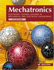
Bolton's course text, published in full as Mechatronics: Electronic Control Systems in Mechanical and Electrical Engineering, is the standard accessible introduction and the right first book: broad, light on mathematics, and organised exactly along the sensor-to-actuator chain. Its bare and subtitled forms are the same catalogue record, so buy either.
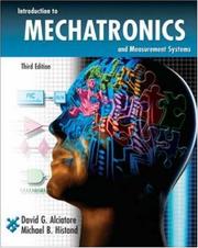
Alciatore and Histand is the more rigorous American counterpart, stronger on circuit analysis, measurement error and instrumentation. Read it second: where Bolton describes, Alciatore derives, and the two together cover the syllabus better than either alone.
The electronics half
IntermediateBecome genuinely competent with the circuits between a sensor and a processor — op-amps, filters, power supplies, motor drivers — and get hands on hardware early rather than after the theory.
▸ Study plan for this stage
Pace: Three to four months, and this stage is a mixture of reading and bench work. Scherz's Practical Electronics for Inventors is 952 pages, but it is a browse-and-build book rather than a course — work through the component and circuit chapters over about six weeks. Horowitz and Hill's The Art of Electr
- The passive foundation done properly: RC and RL time constants, impedance and reactance, filters by order and topology, and why real capacitors and inductors are not the ideal elements in the equations.
- Diodes, bipolar transistors and MOSFETs as devices with datasheets rather than as idealisations — saturation, switching losses, gate charge, thermal limits and derating.
- Operational amplifiers as the workhorse: inverting and non-inverting configurations, difference and instrumentation amplifiers, active filters, and the real-world limits (offset, bias current, slew rate, finite gain-bandwidth) that Horowitz and Hill insist on.
- Power: linear regulators versus switching supplies, decoupling, ground planes and star grounding, and the fact that most beginner mechatronics failures are power and grounding failures rather than logic failures.
- Noise and interference as a design subject: ground loops, common-mode rejection, shielding, differential signalling, and optical or magnetic isolation between the logic side and the motor side.
- Digital interfacing: logic families and levels, level shifting, pull-ups, open-drain outputs, and the standard buses — I2C, SPI, UART — as things with electrical requirements, not just protocols.
- The Horowitz and Hill sensibility, which is the point of reading them: circuits are chosen from a designer's repertoire of known-good arrangements, and the textbook-derived answer is frequently not the one that works on a bench.
- Microcontroller I/O as the meeting point: analogue inputs, PWM outputs, interrupts and timers, which Monk makes concrete in a week and which the rest of the path assumes.
- Design a first-order low-pass filter for a specific sensor bandwidth and state what its output impedance does to whatever you connect next.
- You need to read a millivolt-level differential signal in the presence of a large common-mode voltage. What circuit do you use and why does a plain difference amplifier not suffice?
- What does Horowitz and Hill say about op-amp offset and bias current that changes how you would design a high-impedance sensor front end?
- Why do you never share a ground return between a motor drive and a sensor input, and what specifically goes wrong if you do?
- For driving an inductive load from a microcontroller pin, what is the complete list of things that must be present between the pin and the load?
- Compare I2C and SPI for a specific application: what determines which one you choose, electrically rather than in software?
- Build Scherz's instrumentation-amplifier circuit on a breadboard with his own component values, feed it a known small differential signal, and measure the actual gain against the design value.
- Take one op-amp circuit from Horowitz and Hill, compute its ideal behaviour, then compute the error contributed by the real device parameters from a datasheet you look up yourself. Report the discrepancy as a percentage.
- Work through Monk's Arduino book to a running program that reads one analogue sensor and drives one PWM output, then extend it to log the sensor at a fixed rate using a timer interrupt rather than a delay.
- Drive a small DC motor from a microcontroller through a proper driver stage with a flyback path, then deliberately remove the decoupling capacitor near the microcontroller and record what happens to your sensor readings.
- Design and build a signal-conditioning front end for one of the sensors listed in stage 1 — gain, filter, protection — and characterise its actual bandwidth and noise floor on the bench.
Next up: With working electronics you can now specify components rather than accept whatever the tutorial used, and the next stage is the systematic treatment of the two components that matter most: what senses and what moves.
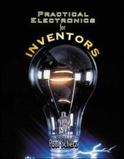
The friendliest bridge from mechanical background to working electronics: components, circuits, and enough theory to stop you guessing. Start the electronics here rather than with a formal circuits textbook, which will slow you down without making you more capable.

Horowitz and Hill is the reference every practising engineer keeps, and it is a design book rather than a physics book — it tells you what circuits actually work and why the textbook answer often does not. Read it after Scherz and use it for the rest of your career.

Placed deliberately in the electronics stage rather than the software one: the fastest way to make the sensor and actuator material real is to build something small this week. Monk's short book is the least ceremonious route to a working circuit under program control.
Sensing, actuation and the mechanical side
IntermediateChoose and characterise the physical components — transducers, motors and drives, linkages and mechanisms — and understand the mechanical design constraints that the electronics cannot fix.
▸ Study plan for this stage
Pace: Three to four months. De Silva's Sensors and Actuators is 847 pages and is the reference-grade treatment of the transduction layer — read the chapters covering the sensor and actuator families you actually use, and treat the rest as lookup. Hughes and Drury's Electric Motors and Drives is 397 pages,
- Transducer characterisation as a discipline: sensitivity, linearity, hysteresis, bandwidth, resolution, noise floor and cross-sensitivity, plus dynamic response — a sensor that is accurate and slow is a control problem, not a measurement problem.
- Sensor selection as a specification exercise. De Silva's contribution is turning 'a strain gauge exists' into 'here is the gauge, the bridge, the excitation, the expected output and the error budget'.
- The control implications of transducer choice: sensor dynamics inside a feedback loop add phase lag, and a poorly chosen sensor limits achievable bandwidth regardless of how good the controller is.
- Motor families and what actually distinguishes them in use: brushed DC, brushless DC and PMSM, induction, stepper, and servo systems as motor-plus-drive-plus-feedback rather than as motors.
- The drive is usually the hard part. Hughes and Drury's central practical point is that power electronics, current control and the supply determine what a motor can do, and mechatronics courses skimp on exactly this.
- Torque-speed characteristics, thermal limits and duty cycle, gearing and reflected inertia, and the inertia-matching argument for sizing a gearbox.
- Mechanism kinematics from Norton: four-bar and slider-crank linkages, position, velocity and acceleration analysis, and the graphical and analytical methods for both.
- Cam design and gear trains, including the pressure-angle and follower-dynamics constraints that determine whether a cam profile is manufacturable.
- For a given position-measurement requirement, work through de Silva's selection criteria and justify a choice between an optical encoder, an LVDT and a potentiometer.
- What does a sensor's own dynamic response do to the phase margin of a feedback loop, and how would you detect that this is your limiting factor?
- Following Hughes and Drury, explain why a stepper motor loses torque with speed and what a chopper drive does about it.
- Given a load inertia and a required acceleration, size a motor and gearbox including reflected inertia, and state the ratio at which the total is minimised.
- For a four-bar linkage, how do you determine whether a given set of link lengths produces a crank-rocker, and what is the Grashof condition?
- Why does cam follower jump occur, and what in the cam profile and the spring preload controls it?
- Take one sensor you have physically used, fill in de Silva's full characterisation table for it from its datasheet, and then measure at least two of those parameters on the bench to see whether the datasheet is telling the truth.
- Reproduce Hughes and Drury's torque-speed calculation for a specific motor with their own numbers, then repeat it for a motor you can actually buy, using its published curve, and size it for a real load.
- Work a complete position, velocity and acceleration analysis of a four-bar linkage from Norton, analytically, then check your result against a numerical simulation you write yourself.
- Design a cam profile in Norton's framework for a specified follower motion, compute the pressure angle across the cycle, and report whether it stays within his recommended limit.
- Choose a real mechanism — a printer carriage, a pick-and-place arm — and produce a complete actuator specification for it: torque, speed, inertia, duty cycle, drive type and sensor, with the arithmetic shown.
- Do Norton's dynamic force analysis on a slider-crank at a chosen operating speed and compute the shaking force, then state what balancing measure would reduce it.
Next up: You now have hardware that can sense and move; the next stage is the firmware that runs it and the control theory that decides what it should do.
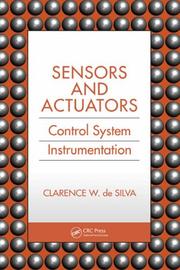
The systematic treatment of the transduction layer: sensor physics, error and calibration, actuator selection, and the control implications of each choice. The book to read when your survey course has told you a strain gauge exists and you now have to specify one.
Hughes and Drury explain motors and their power electronics in plain engineering language, without the machine-theory apparatus that makes most texts unusable for a designer. Read it before you choose a motor for anything — the drive is usually the hard part, and it is the part mechatronics courses skimp on.
The mechanical half that mechatronics courses assume you already have: linkages, cams, gears, and the kinematic and dynamic analysis of mechanisms. Here because a mechatronic system is only as good as the machine it actuates, and this is the standard text on designing that machine.
Embedded software and control
IntermediateWrite software that runs on a microcontroller under real-time constraints, and design the feedback loops — PID and beyond — that make the system behave.
▸ Study plan for this stage
Pace: Three to four months. Elecia White's Making Embedded Systems is 330 pages and should be read first, in about three weeks, and read before any control theory — it treats embedded software as a practice rather than a syntax exercise. Nise's Control Systems Engineering is 880 pages and is a full semest
- Embedded architecture before code: interrupts and interrupt latency, main-loop versus state-machine versus scheduler structure, and why blocking delays destroy real-time behaviour.
- Designing firmware you can still change in a year: hardware abstraction layers, driver interfaces, and separating device specifics from application logic. This is White's central argument and the reason her book precedes the control theory.
- Modelling for control: transfer functions from differential equations, block-diagram reduction, poles and zeros, and the correspondence between pole locations and time-domain behaviour.
- Time-domain specification and steady-state error: rise time, overshoot, settling time, system type and error constants — the vocabulary in which a control requirement is actually written.
- Root locus as the design tool for understanding how closed-loop poles migrate with gain, and the compensator forms — lead, lag, PID — built on that understanding.
- Frequency response, Bode and Nyquist, gain and phase margin, and stability robustness as the quantity you are really buying with a compensator.
- PID in practice: what each term does, integral windup and its anti-windup fixes, derivative kick and filtering, and tuning methods versus model-based design.
- State-space representation, controllability and observability, pole placement and the observer — Nise's later chapters, and the language in which modern and multivariable control is written.
- Why does a delay loop inside an interrupt handler break a real-time system, and what is White's structural alternative?
- Given a second-order transfer function, predict the overshoot and settling time from the pole locations, then say what changing the damping ratio does to each.
- Sketch the root locus for a specific plant and gain range, and identify the gain at which the closed-loop system becomes unstable.
- What do gain margin and phase margin mean physically, and what specifically has gone wrong in a system that meets its overshoot spec but has a phase margin of ten degrees?
- Explain integral windup in a real actuator with a saturation limit, and describe two different anti-windup schemes.
- For a plant Nise treats in state space, check controllability and observability and say what a failure of either means you cannot do.
- Restructure a piece of Arduino code you wrote in stage 2 from a delay-driven main loop into an interrupt-driven state machine following White's pattern, and measure the change in worst-case response latency.
- Write a hardware abstraction layer for one sensor and one actuator, then swap the underlying part for a different one and confirm the application code does not change.
- Take one of Nise's full case studies — the antenna azimuth position control system runs through the whole book — and work it end to end with his own parameter values, reproducing his root locus, his compensator design and his simulated step response.
- Derive the transfer function of a DC motor with the electrical and mechanical parameters of a motor you specified in stage 3, then design a PID controller for it in Nise's framework.
- Implement that controller in fixed-point arithmetic on a microcontroller, with anti-windup and derivative filtering, and compare the measured step response against your simulation. Account for every discrepancy.
- Deliberately add a one-sample computational delay to your digital controller and measure how much phase margin it costs, then confirm the number against the analytical prediction.
Next up: Subsystems that individually work do not make a working machine; the last stage is the design process that integrates them, plus the field mechatronics turns into next.
The best available book on embedded software as a practice rather than a syntax exercise: interrupts, state machines, memory constraints, debugging without a debugger, and designing firmware you can still change in a year. Read it before any control theory.
The standard undergraduate control text, and the more approachable of the two mainstream options — transfer functions, root locus, frequency response, PID design, state space, with worked case studies throughout. This is the control theory a mechatronics engineer actually uses; read it once the hardware is real enough to apply it to.
Whole-system design, and where it leads
IntermediatePut the pillars back together on a real project, learn the systematic design and modelling methods, and see where mechatronics opens into robotics.
▸ Study plan for this stage
Pace: Four to six months, and most of it should be spent building. Carryer, Kenny and Ohline's Introduction to Mechatronic Design is 816 pages and came out of Stanford's project course — read it while building something, not before, taking chapters as the corresponding decision arrives. Shetty and Kolk's
- Design as sequenced decision-making: requirements, concept selection, interface definition, and the specific order in which mechatronic choices constrain each other — actuator before structure, sensor before controller, power before everything.
- Integration failures as the characteristic mechatronic problem. Carryer's value is that he covers the things survey texts never mention: connector choice, wire routing, mechanical tolerance stack-up, EMI between the drive and the logic, and what to do when the subsystems each pass their own test and
- Shetty and Kolk's formal side: system modelling across domains, simulation before build, real-time interfacing, and treating the design process as a documented sequence rather than an improvisation.
- Hardware-in-the-loop and staged verification — testing a controller against a simulated plant before risking hardware, and knowing which fidelity of model is enough.
- Rigid-body pose in Craig's notation: rotation matrices, homogeneous transformations, and the Denavit-Hartenberg convention for describing a manipulator's geometry.
- Forward and inverse kinematics — the difference in difficulty between them, multiple solutions, workspace boundaries and singularities.
- The Jacobian as the map between joint rates and end-effector velocity, its role in static force transmission, and what a singular Jacobian means for a real arm.
- Trajectory generation and manipulator dynamics, leading into manipulator control: computed-torque and independent-joint control, and where the linear control of stage 4 stops being adequate.
- Carryer covers decisions in the order they arise in a project. What is the earliest decision in a mechatronic design that is genuinely irreversible, and why?
- What does Shetty and Kolk's formal modelling step catch that Carryer's build-and-iterate approach would only reveal on hardware?
- Derive the forward kinematics of a three-link planar arm using homogeneous transforms, and then state how many inverse-kinematic solutions exist and where.
- What physically happens to a manipulator at a kinematic singularity, and what does the Jacobian's rank tell you about it?
- Compare independent-joint PID control with computed-torque control for a fast-moving arm: what specifically does the linear approach fail to account for?
- Looking back over the whole path, which stage supplied the constraint that most limited your last project?
- Build one complete mechatronic device end to end, following Carryer's project structure: written requirements, actuator sizing from stage 3, a designed and characterised sensor front end from stage 2, firmware structured per White, and a controller designed per Nise. Keep a decision log.
- Before building it, produce a Shetty-and-Kolk-style cross-domain simulation of the same device, then afterwards tabulate every place the simulation and the hardware disagreed and diagnose why.
- Use Bishop's handbook to answer three specific questions your project raised that none of the course texts covered, and note in each case what the handbook gave you that they did not.
- Work Craig's forward and inverse kinematics for a specific manipulator with his own Denavit-Hartenberg parameters, verify your inverse solutions numerically by feeding them back through the forward map, and reproduce his reported results.
- Compute the Jacobian for that manipulator, find a singular configuration analytically, and demonstrate numerically that joint rates blow up as you approach it along a straight-line end-effector path.
- Generate a joint-space trajectory with Craig's cubic-polynomial method for a specified move, then a straight-line Cartesian trajectory for the same move, and compare the joint velocities each demands.
Next up: The path ends where mechatronics becomes robotics: with Craig's kinematics and manipulator control in hand, the natural next reading is robot dynamics and motion planning, real-time embedded systems, and modern multivariable and optimal control.

Carryer, Kenny and Ohline wrote this out of Stanford's project course, and it is the most project-driven book on this list: it is organised around the decisions you make while building something, including the ones the survey texts never mention. Read it while building, not before.
Shetty and Kolk supply the systematic modelling and simulation methodology — system modelling, real-time interfacing, and the design process as a formal sequence — that Carryer's hands-on approach deliberately leaves loose. The two are complementary.
The professional reference volume, organised for lookup across every subsystem from MEMS to motion control to software. Own it rather than read it; it is where you check a topic the course books treated in half a page.
Craig's book is where mechatronics turns into robotics: forward and inverse kinematics, Jacobians, trajectory generation and manipulator control. Closes the path because it is the natural next subject, and because it assumes precisely the mechanics-plus-control combination the previous stages built. Catalogued under the bare title 'Introduction to robotics'.
Discussion
Keep reading
Paths that share books, cover the same subject, or open a related topic.