Build things with Arduino
This curriculum takes a complete beginner from zero electronics knowledge to confident, project-driven Arduino mastery. Each stage builds on the last — first establishing core electronics intuition, then introducing Arduino hands-on, then deepening programming and circuit design skills, and finally tackling real-world maker projects and independent creation.
Foundations: How Electricity Works
BeginnerUnderstand voltage, current, resistance, and basic circuit concepts well enough to read schematics and not fry components.
▸ Study plan for this stage
Pace: 6–8 weeks total. Week 1–2: Read "Electricity for Young Makers" cover to cover (~15–20 pages/day, including pausing to sketch diagrams). Weeks 3–8: Work through "Make More Electronics" at ~20–25 pages/day, but treat it as a lab manual — never read more than one chapter ahead of your bench work.
- Voltage (V): the 'pressure' that pushes electrons through a circuit — introduced intuitively in de Vinck through water-flow analogies before formalizing with Ohm's Law
- Current (I): the rate of electron flow measured in amperes, and why exceeding a component's current rating destroys it
- Resistance (R): opposition to current flow; how resistors protect LEDs and other components — a central hands-on theme in both books
- Ohm's Law (V = I × R): the single most important formula at this stage; de Vinck introduces it gently, Platt reinforces it with real measurements
- Series vs. parallel circuits: how voltage divides in series and current divides in parallel — Platt's early experiments make this tangible
- Reading and drawing schematics: standard symbols for resistors, capacitors, LEDs, switches, and power supplies as used throughout both books
- Power dissipation (P = V × I): understanding why a resistor can overheat and how to choose the right wattage rating, covered in Platt's component deep-dives
- Capacitors and basic RC behavior: charge/discharge cycles introduced in Make More Electronics as a bridge toward timing and filtering concepts
- Given a 9 V supply and an LED that needs 20 mA, how do you calculate the correct current-limiting resistor value using Ohm's Law?
- What is the difference between connecting two resistors in series versus in parallel, and how does each configuration affect total resistance and current?
- Why does a short circuit cause components (or batteries) to overheat, and what does Ohm's Law tell you about what happens to current when resistance approaches zero?
- Looking at a schematic from either book, can you identify and name every standard symbol present — resistor, capacitor, LED, switch, ground, and VCC?
- What does a capacitor do in a simple RC circuit, and how does changing the resistor value affect how quickly the capacitor charges?
- How do you use a multimeter to measure voltage across a component and current through a branch, and why must you wire it differently for each measurement?
- **Ohm's Law triangle drill (de Vinck):** After finishing de Vinck, pick five different resistor values from your kit, connect each to a 5 V or 9 V supply, measure the actual current with a multimeter, and compare your measured value to the V = IR prediction. Log the results in a notebook.
- **LED resistor calculator (de Vinck → Platt):** Wire at least four different colored LEDs (each has a slightly different forward voltage). Calculate the correct resistor for each, build the circuit, verify the LED is not too dim or too bright, and record forward voltage, chosen resistor, and measured current.
- **Series vs. parallel resistor lab (Platt):** Build a series chain of three resistors, measure total resistance and voltage across each one. Rebuild them in parallel and repeat. Confirm your measurements match the theoretical formulas from Platt's text.
- **Schematic redraw exercise:** Choose any three completed circuits from either book and redraw the schematic from scratch — without looking at the book's version — then compare yours to the original for symbol accuracy and correctness.
- **RC timing observation (Platt):** Build the basic RC charge/discharge circuit from Make More Electronics. Swap in at least three different resistor values and use an LED or multimeter to observe how the timing changes. Sketch a qualitative charge curve for each.
- **Component autopsy & power rating check:** Intentionally (and safely, with a current-limited bench supply or a large resistor in series) over-stress a sacrificial low-watt resistor to see it heat up. Calculate beforehand using P = V × I what wattage it is dissipating, and confirm it exceeds its rating — reinforcing why wattage selection matters.
Next up: Mastering voltage, current, resistance, and schematic reading here gives you the essential 'vocabulary' so that the next stage — introducing microcontrollers and Arduino I/O — makes immediate sense: every pin voltage, current limit, and pull-up resistor you encounter will be an application of exactly these foundations.

A gentle, visual introduction to electricity and basic components — ideal first read that builds physical intuition without overwhelming math.
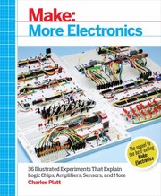
The definitive hands-on beginner electronics book; learn-by-doing experiments with resistors, capacitors, and transistors give you the tactile foundation every Arduino project depends on.
Hello Arduino: First Projects
BeginnerSet up an Arduino, write and upload sketches, and complete a range of guided beginner projects with confidence.
▸ Study plan for this stage
Pace: 10–12 weeks total. Week 1–3: "Arduino For Beginners Essential Skills Every Maker Needs" by Baichtal (~20–25 pages/day), focusing on hardware orientation and first sketches. Week 4–6: "Getting Started with Arduino" by Banzi (~15–20 pages/day), reading slowly and experimentally — pause to run every ex
- The Arduino hardware ecosystem: board anatomy (pins, power, microcontroller), IDE setup, and the upload workflow — as introduced in Baichtal's foundational chapters
- The structure of an Arduino sketch: setup() vs. loop(), and why this event-loop model is central to all Arduino programming (Banzi & Baichtal)
- Digital I/O: using pinMode(), digitalWrite(), and digitalRead() to control LEDs, buttons, and other simple components (all three books)
- Analog I/O: reading sensors with analogRead() and controlling brightness/speed with analogWrite() PWM — explored practically in Banzi and extended in Margolis's Cookbook recipes
- Serial communication: using Serial.begin() and Serial.println() to debug sketches and read sensor data in the Serial Monitor (Banzi, Margolis)
- Basic circuit concepts for makers: voltage, current, resistance, Ohm's Law, breadboarding, and reading simple schematics — grounded in Baichtal's maker-oriented explanations
- Working with common components: LEDs, resistors, pushbuttons, potentiometers, servos, and basic sensors, as covered across all three books' guided projects
- Using and adapting existing code: reading Cookbook-style recipes, modifying parameters, combining sketches, and developing the habit of incremental experimentation (Margolis)
- Can you describe every labeled part of an Arduino Uno board and explain the purpose of the digital pins, analog pins, power pins, and USB port, as outlined in Baichtal?
- What is the role of setup() versus loop() in an Arduino sketch, and what would happen if you placed your entire program inside setup() only — as Banzi's introductory examples illustrate?
- How do you calculate the correct resistor value for an LED circuit using Ohm's Law, and why does Baichtal emphasize this as a foundational maker skill?
- What is the difference between digitalRead()/digitalWrite() and analogRead()/analogWrite(), and when would you choose one over the other based on the projects in Banzi and Margolis?
- How does the Serial Monitor help you debug a sketch, and can you walk through a concrete example from Margolis's Cookbook where serial output reveals what a sensor is doing?
- How would you take a recipe from the Arduino Cookbook, adapt one of its parameters (e.g., timing, pin number, threshold), and predict how the circuit's behavior would change?
- Hardware scavenger hunt (Baichtal): Label every pin and component on a physical or printed diagram of an Arduino Uno from memory, then verify against Baichtal's board overview. Repeat until you can do it in under two minutes.
- Blink variations (Banzi): Start with Banzi's classic Blink sketch, then modify it in five different ways — change delay values, add a second LED on a different pin, make an SOS pattern in Morse code — uploading and observing each change.
- Breadboard circuit log (Baichtal + Banzi): Build five different circuits on a breadboard (e.g., LED with resistor, button-controlled LED, voltage divider with potentiometer) and sketch each one in a notebook with component values and pin assignments recorded.
- Sensor serial dashboard (Banzi + Margolis): Wire up a potentiometer and at least one additional analog sensor (e.g., photoresistor or temperature sensor from a Cookbook recipe), then write a sketch that prints all readings to the Serial Monitor in a labeled, human-readable format every 500 ms.
- Cookbook remix project (Margolis): Choose any three recipes from the Arduino Cookbook that interest you, build each one exactly as written, then combine elements from at least two of them into a single original sketch — for example, using a button press to trigger a servo movement with LED feedback.
- Project journal: After completing each major project across all three books, write a short entry (5–10 sentences) describing what the project does, what went wrong, how you fixed it, and one way you could extend it further. Review all entries at the end of week 12.
Next up: Completing these three books gives you a confident, hands-on command of core Arduino I/O and sketch structure, which is the essential foundation for the next stage — where you'll move beyond guided projects into more complex sensors, communication protocols (I2C, SPI, serial), and designing your own original circuits from scratch.
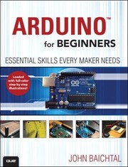
A friendly, step-by-step introduction to the Arduino ecosystem — covers the IDE, basic sketches, and wiring before any other Arduino book to avoid early confusion.
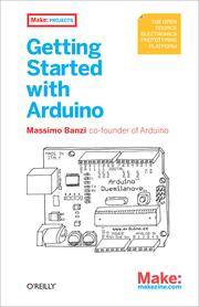
Written by Arduino's co-founder, this compact book explains the philosophy and workflow of Arduino and solidifies the core loop of sense → process → actuate.

A problem-solution reference that expands your toolkit rapidly; read it project-by-project after Banzi to learn how to handle sensors, motors, displays, and serial communication.
Going Deeper: Code & Circuits
IntermediateWrite cleaner, more structured Arduino code, read datasheets, and design your own circuits rather than just following diagrams.
▸ Study plan for this stage
Pace: 8–10 weeks total: Weeks 1–3 cover "Programming Arduino" by Simon Monk (~30–40 pages/day, reading alongside active sketching on hardware); Weeks 4–10 cover "Practical Electronics for Inventors" by Paul Scherz (~25–35 pages/day, pausing frequently to work through calculations and breadboard experiment
- Structured Arduino sketching: separating setup(), loop(), and helper functions for readability and reuse (Monk)
- Data types, arrays, and strings in C/C++ as used in Arduino sketches — avoiding memory pitfalls on a microcontroller (Monk)
- Interrupts and timing: using millis() instead of delay(), and hardware interrupts for responsive programs (Monk)
- Libraries: how to install, read, and write your own Arduino libraries to encapsulate reusable functionality (Monk)
- Ohm's Law, Kirchhoff's Voltage and Current Laws, and how to apply them to real circuit analysis rather than just copying diagrams (Scherz)
- Passive components in depth: resistors, capacitors, and inductors — their behavior in DC and AC circuits, including RC time constants and filtering (Scherz)
- Semiconductor fundamentals: diodes, BJTs, and MOSFETs — reading a datasheet to extract V_BE, V_GS(th), I_D ratings, and pinouts (Scherz)
- Datasheet literacy: locating absolute maximum ratings, electrical characteristics tables, and application circuits to safely integrate ICs and discrete components (Scherz)
- After reading Monk, can you explain why replacing delay() with millis()-based timing makes a sketch more responsive, and rewrite a simple blink sketch to demonstrate it?
- How does Monk's approach to writing custom libraries change the way you organize a multi-file Arduino project, and what files are required for a minimal library?
- Using the laws covered in Scherz, how would you calculate the correct current-limiting resistor for an LED driven from a 5 V Arduino pin, given the LED's forward voltage and desired current?
- What is an RC low-pass filter, and — drawing on Scherz — how do you calculate its cutoff frequency? Where might you use one in an Arduino project?
- Given a BJT datasheet, how do you determine whether the transistor is in saturation, and why does that matter when using it as a switch to drive a motor from an Arduino output pin?
- How do you find and interpret the 'Absolute Maximum Ratings' section of a datasheet (as taught by Scherz), and what happens if you exceed those values?
- **Monk — Refactor Challenge:** Take any sketch you wrote during the beginner stage and rewrite it using Monk's structured style: break it into named helper functions, eliminate all delay() calls in favor of millis(), and add comments explaining each section.
- **Monk — Custom Library:** Build a small Arduino library (a .h and .cpp file pair) that encapsulates control of an RGB LED — exposing functions like setColor(r, g, b) and fadeToColor() — following the library structure Monk describes.
- **Monk — Interrupt-Driven Button:** Wire a pushbutton to an interrupt-capable pin and use attachInterrupt() to toggle an LED state without polling in loop(). Log the event count to Serial and verify no presses are missed.
- **Scherz — Paper Circuit Analysis:** Before touching a breadboard, draw three different resistor networks (series, parallel, and mixed), calculate all node voltages and branch currents by hand using KVL/KCL, then verify with a multimeter on the actual built circuit.
- **Scherz — Datasheet Scavenger Hunt:** Download the datasheet for a component you already own (e.g., a 2N2222 BJT or a common MOSFET). Locate and record: pinout, V_CE(sat), h_FE range, absolute maximum ratings, and a reference application circuit. Then use those values to design a transistor switch that drives a 5 V relay from an Arduino pin.
- **Scherz — RC Filter Build & Measure:** Design an RC low-pass filter for a cutoff frequency of ~1 kHz using values from Scherz's formula. Build it, feed it a square wave from the Arduino's PWM output, and use Serial + analogRead() (or an oscilloscope if available) to observe the filtered output and compare it to your calculated prediction.
Next up: Mastering structured code in Monk and the underlying electronics theory in Scherz gives you the vocabulary and confidence to tackle more complex, self-designed projects — making the next stage, which focuses on sensors, communication protocols, and system-level design, feel like a natural application of these foundations rather than a leap into the unknown.

Focuses specifically on the C/C++ programming side of Arduino — functions, libraries, interrupts, and memory — bridging the gap between copy-paste sketches and real software thinking.
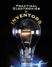
The go-to intermediate electronics reference; after hands-on Arduino experience, this book gives you the underlying theory (op-amps, transistors, ICs) needed to design original circuits.
Real-World Projects & Maker Mastery
ExpertBuild complex, polished projects integrating networking, sensors, and custom PCBs, and develop the mindset to design from scratch.
▸ Study plan for this stage
Pace: 6–8 weeks, ~25–35 pages/day — Hughes is dense with reference material, so alternate between reading new chapters and revisiting earlier sections as you build projects. Dedicate weekdays to reading and weekends to hands-on project work.
- Deep hardware architecture of the Arduino platform — registers, timers, interrupts, and memory maps as documented in Hughes' technical reference
- Precise pin and peripheral specifications: understanding voltage tolerances, current limits, PWM channels, and analog reference configurations for robust circuit design
- Serial communication protocols in depth — UART, SPI, I2C, and USB — including timing, addressing, and error handling as covered by Hughes
- Power supply design and management: voltage regulation, decoupling capacitors, and powering Arduino from batteries, solar, or custom rails
- Networking and connectivity integration: leveraging shields and modules (Ethernet, Wi-Fi) with a firm grasp of the underlying electrical and software interfaces
- Sensor interfacing at a hardware level — signal conditioning, ADC resolution and sampling, and noise reduction techniques
- Custom PCB design mindset: translating a breadboard Arduino circuit into a standalone, production-quality schematic using Hughes' schematic and pinout references as a blueprint
- Design-from-scratch methodology: reading datasheets, cross-referencing Hughes' technical tables, and making deliberate component and architecture choices
- Given a specific Arduino variant (e.g., Uno vs. Mega vs. Leonardo), how do you use Hughes' reference tables to identify which pins share timer or interrupt resources, and why does that matter for a multi-sensor project?
- How do the electrical specifications in Hughes (voltage levels, source/sink current limits, analog reference options) directly influence PCB layout decisions and component selection?
- Walk through the configuration of SPI and I2C on a chosen Arduino board using Hughes' register and peripheral maps — what are the key parameters to set, and what failure modes should you anticipate?
- How would you design a power subsystem for a battery-operated, networked Arduino device, drawing on the power characteristics documented by Hughes?
- Using Hughes as a reference, how do you systematically debug a hardware fault — for example, a sensor returning noisy or incorrect ADC readings — at the register and circuit level?
- What is the process for 'graduating' a breadboard prototype to a custom PCB, and how does Hughes' technical reference serve as the authoritative source during schematic capture and design review?
- **Peripheral Audit Project:** Choose a complex Arduino variant (e.g., Mega 2560). Using only Hughes' pinout and register tables, create a full annotated diagram mapping every timer, interrupt, SPI/I2C/UART line, and PWM channel — then design a project that deliberately uses at least one resource from each category simultaneously.
- **Networked Sensor Node:** Build a Wi-Fi or Ethernet-connected device that reads at least two different sensor types (e.g., temperature + light). Use Hughes' ADC and communication protocol specs to validate your wiring and write register-level initialization code rather than relying solely on high-level libraries.
- **Power Budget Analysis:** For a real project you've built, calculate the full power budget (microcontroller, sensors, communication module, LEDs) using the electrical specs in Hughes. Then redesign the power subsystem to run on a LiPo battery for a target duration of 24 hours.
- **Custom Shield Design:** Using Hughes' schematic symbols, pinouts, and electrical specs as your sole reference, design a custom Arduino shield on paper (or in KiCad/EasyEDA) that breaks out SPI, I2C, and two analog inputs to a set of labeled headers — perform a design review checklist against Hughes' specs before 'signing off'.
- **Interrupt-Driven State Machine:** Rewrite an existing polling-based project to use hardware interrupts and timer-based scheduling as described in Hughes. Benchmark and document the difference in responsiveness and CPU utilization.
- **Datasheet + Hughes Cross-Reference Drill:** Pick a sensor or module you've never used. Read its datasheet, then cross-reference every electrical and protocol requirement against Hughes' Arduino reference tables to produce a one-page integration checklist before writing a single line of code or making a single connection.
Next up: Mastering Hughes' technical reference transforms the reader from a sketch-level programmer into a hardware-literate engineer, providing the rigorous foundation in electronics, protocols, and architecture needed to confidently tackle fully custom embedded systems design, FPGA exploration, or professional product development beyond the Arduino ecosystem.

A comprehensive, engineer-level reference covering hardware registers, shields, and interfacing in depth — the book to keep on your desk when building serious, reliable projects.
Discussion
Keep reading
Paths that share books, cover the same subject, or open a related topic.