Electronics and circuits: the best books to learn how they work, in order
This curriculum takes a complete beginner from the fundamental intuitions of voltage, current, and resistance all the way through analog circuit design and digital logic, culminating in hands-on project-based work. Each stage builds directly on the last — conceptual vocabulary first, then mathematical depth, then real design skills — so no step feels like a leap.
Foundations: Intuition & First Principles
BeginnerUnderstand what electricity is, how voltage, current, and resistance relate, and gain the confidence to read a simple schematic and think like an engineer.
▸ Study plan for this stage
Pace: 4–5 weeks, ~25–30 pages/day. Start with "Electricity Demystified" (2 weeks), then transition to "Make More Electronics" (2–3 weeks) for hands-on reinforcement.
- Electric charge, current flow, and conventional vs. electron flow direction
- Voltage as electrical potential difference and energy per unit charge
- Resistance and Ohm's Law (V = IR) as the fundamental relationship between voltage, current, and resistance
- Power dissipation and energy consumption in circuits
- Series and parallel circuit configurations and how they affect total resistance and current distribution
- Reading and interpreting schematic symbols, component identification, and circuit diagrams
- Practical measurement with multimeters and basic troubleshooting mindset
- Safety principles: working with batteries, avoiding short circuits, and respecting electrical hazards
- What is the difference between voltage, current, and resistance, and how do they relate mathematically?
- How do series and parallel circuits differ in terms of voltage drop, current distribution, and total resistance?
- What does a schematic symbol represent, and can you identify common components (resistors, LEDs, batteries, switches) in a circuit diagram?
- How do you use a multimeter to measure voltage and current, and what does each reading tell you about circuit behavior?
- Why does current flow in a circuit, and what role does resistance play in limiting or controlling that flow?
- How can you predict whether a component will work correctly in a circuit using Ohm's Law and power calculations?
- Build a simple series circuit with a battery, resistor, and LED using a breadboard; measure voltage across each component and verify Ohm's Law.
- Construct a parallel circuit with two resistors and compare total resistance to individual resistances; explain why the total is lower.
- Use a multimeter to measure voltage, current, and resistance in a working circuit; record data and identify any anomalies.
- Sketch schematics for three circuits you've built, labeling all components and using correct symbols.
- Modify a circuit by changing resistor values and predict the effect on brightness (for an LED) or current draw before measuring.
- Troubleshoot a deliberately broken circuit (e.g., a loose connection or burnt resistor) by systematically measuring voltage and current to locate the fault.
Next up: Mastering these foundations—Ohm's Law, circuit topology, and schematic literacy—prepares you to tackle component-specific behavior (diodes, transistors, capacitors) and more complex circuit design in the next stage.

A gentle, jargon-free introduction to electrical concepts that builds intuition before any math. Perfect as the very first book to remove fear of the subject.
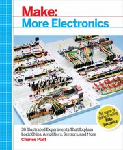
Immediately grounds theory in hands-on experiments with real components. Reading it alongside Gibilisco connects abstract ideas to physical reality from day one.
Core Theory: DC & AC Circuit Analysis
BeginnerMaster Ohm's Law, Kirchhoff's Laws, and the behavior of resistors, capacitors, and inductors in both DC and AC circuits — the mathematical backbone of all electronics.
▸ Study plan for this stage
Pace: 8–10 weeks, ~40–50 pages/day. Start with "Fundamentals of Electric Circuits" (Chapters 1–8, approximately 4–5 weeks), then transition to "The Art of Electronics" (Chapters 1–3, approximately 3–5 weeks) for practical reinforcement and deeper intuition.
- Ohm's Law (V=IR) and its applications in series and parallel circuits
- Kirchhoff's Voltage Law (KVL) and Kirchhoff's Current Law (KCL) for circuit analysis
- Node voltage and mesh current methods for solving multi-loop circuits
- Resistor behavior in DC circuits: series/parallel combinations and voltage/current dividers
- Capacitor behavior in DC (charging/discharging) and AC circuits (impedance, phase relationships)
- Inductor behavior in DC (steady-state) and AC circuits (impedance, phase relationships)
- Phasor representation and complex impedance for AC circuit analysis
- Thevenin and Norton equivalent circuits for circuit simplification
- How do you apply Ohm's Law to find unknown voltage, current, or resistance in a simple circuit?
- State Kirchhoff's Voltage Law and Kirchhoff's Current Law, and explain how to use them to analyze a multi-loop circuit.
- What is the difference between how resistors, capacitors, and inductors behave in DC versus AC circuits?
- How do you calculate equivalent resistance for resistors in series and parallel configurations?
- What is impedance, and how does it differ from resistance? How do capacitors and inductors contribute to impedance in AC circuits?
- Explain the concept of phasors and how they simplify AC circuit analysis.
- What are Thevenin and Norton equivalents, and why are they useful for circuit analysis?
- How do you use node voltage or mesh current methods to solve a circuit with multiple loops and sources?
- Solve 10–15 resistor network problems from 'Fundamentals' (Chapters 2–3) using series/parallel rules and voltage/current dividers.
- Apply KVL and KCL to analyze 5–8 multi-loop DC circuits, then verify solutions using node voltage and mesh current methods.
- Build and measure a simple RC circuit (resistor + capacitor) in hardware or simulation; observe charging/discharging behavior and compare to theoretical predictions.
- Solve 8–10 AC circuit problems involving capacitors and inductors using phasor notation and complex impedance from 'Fundamentals' (Chapters 9–10).
- Work through 5–6 Thevenin/Norton equivalent problems from 'Fundamentals' (Chapter 4) and verify by simulation or breadboard.
- Complete the practical circuits and measurement exercises from 'The Art of Electronics' (Chapters 1–3), such as building a simple amplifier stage or filter circuit and measuring frequency response.
- Solve mixed DC/AC problems that combine multiple concepts (e.g., a circuit with resistors, capacitors, and a sinusoidal source).
- Use circuit simulation software (SPICE, LTspice, or similar) to model and verify 5–6 hand-calculated circuits, building confidence in both theory and tools.
Next up: This stage equips you with the mathematical and conceptual foundation to analyze any linear circuit, preparing you to move into component-level design, amplifier circuits, and frequency response analysis in the next stage.

The most widely adopted university-level circuits textbook. Its clear worked examples and problem sets turn the intuitions from Stage 1 into rigorous, transferable skills.
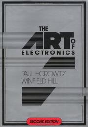
A legendary reference that bridges pure theory and practical design. Reading selected chapters here after Alexander shows how real engineers think about the same equations.
Analog Electronics: Components & Design
IntermediateUnderstand diodes, transistors, and op-amps deeply enough to analyze and design amplifiers, filters, and power supplies from scratch.
▸ Study plan for this stage
Pace: 8–10 weeks, ~40–50 pages/day. Spend 5–6 weeks on Neamen's foundational chapters (diodes, BJTs, FETs, basic amplifiers); then 2–3 weeks on Jung's Op Amp Handbook for practical circuit design and applications.
- Diode physics and operation: forward/reverse bias, I-V characteristics, and the Shockley equation; applications in rectifiers and voltage regulation
- BJT and FET fundamentals: device structure, biasing, small-signal models, and transconductance; DC and AC analysis in common-emitter/source configurations
- Transistor amplifier design: gain calculations, input/output impedance, frequency response, and stability; designing for specified gain and bandwidth
- Op-amp ideal and non-ideal behavior: gain, bandwidth, slew rate, input/output impedance, and frequency compensation; closed-loop vs. open-loop operation
- Negative feedback in amplifiers: how it stabilizes gain, reduces distortion, and sets input/output impedance; loop gain and stability margins
- Filter design fundamentals: first and second-order passive and active filters; Bode plots, cutoff frequencies, and filter topologies (Sallen-Key, inverting integrator)
- Power supply design: rectification, filtering, and regulation using Zener diodes and linear regulators; ripple voltage and efficiency calculations
- Practical circuit implementation: component selection, PCB layout considerations, and troubleshooting amplifiers and filters in real designs
- Derive the small-signal model for a BJT in the active region and explain how it predicts voltage gain in a common-emitter amplifier.
- Design a two-stage amplifier with specified voltage gain and bandwidth; calculate component values and verify stability using Bode plots.
- Explain the role of negative feedback in an op-amp circuit: how does it affect closed-loop gain, input impedance, and bandwidth?
- Compare the frequency response of first-order RC and active (op-amp) filters; when would you choose one over the other?
- Design a full-wave rectifier with LC filtering and linear voltage regulation; calculate ripple voltage and dropout voltage requirements.
- Analyze a practical op-amp circuit (e.g., inverting amplifier or Sallen-Key filter) for non-ideal effects: finite gain, bandwidth limitations, and slew-rate constraints.
- Work through Neamen's diode problems (Chapter 2): analyze rectifier circuits, calculate peak inverse voltage, and design Zener regulators for specified load conditions.
- Solve BJT biasing problems from Neamen (Chapter 4): design DC bias networks for common-emitter amplifiers with specified quiescent points; verify using load-line analysis.
- Design a small-signal BJT amplifier (Neamen Chapter 6): choose biasing resistors, calculate voltage gain, input/output impedance, and -3dB bandwidth; simulate or breadboard to verify.
- Analyze FET amplifiers (Neamen Chapter 7): compare JFET and MOSFET biasing; design a common-source amplifier and measure its frequency response.
- Build a two-stage amplifier circuit: cascade a BJT preamp with an op-amp gain stage (using Jung's Handbook); measure overall gain, noise figure, and frequency response.
- Design and simulate an active filter (low-pass Sallen-Key or inverting integrator from Jung): verify cutoff frequency, rolloff rate, and phase response against design calculations.
Next up: This stage equips you with the component-level understanding and design skills needed to move into power electronics, RF circuits, or mixed-signal systems—where you'll apply these amplifier and filter principles to switching supplies, impedance matching networks, or integrated signal chains.
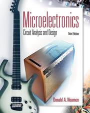
Provides a thorough, device-level treatment of diodes and transistors (BJT and MOSFET) with clear derivations — the essential next step after mastering passive circuits.

The definitive practical guide to op-amps. After learning transistor theory, this book shows how to use the most important analog building block in real designs.
Digital Logic & Systems
IntermediateUnderstand binary logic, Boolean algebra, combinational and sequential circuits, and how digital systems are built from gates up to microprocessors.
▸ Study plan for this stage
Pace: 8–10 weeks, ~40–50 pages/day (Mano first 4–5 weeks, Clark 3–4 weeks, plus review and projects)
- Binary number systems and Boolean algebra as the foundation of digital logic
- Logic gates (AND, OR, NOT, NAND, NOR, XOR) and their truth tables as building blocks
- Combinational circuits: design, minimization, and implementation (multiplexers, decoders, adders)
- Sequential circuits: latches, flip-flops, and state machines that introduce memory and timing
- Registers, counters, and shift registers as practical sequential building blocks
- Microprocessor architecture: how ALUs, control units, and memory work together
- The complete digital system pipeline from gates → combinational logic → sequential logic → CPU
- Timing, clock signals, and synchronization in digital systems
- How do you convert between binary, decimal, and hexadecimal, and why is this essential for digital design?
- What is Boolean algebra, and how do you use it to simplify logic expressions and design circuits?
- What is the difference between combinational and sequential circuits, and what role does feedback play?
- How do flip-flops work, and why are they necessary for building memory and state machines?
- How does a microprocessor execute instructions, and what are the roles of the ALU, control unit, and registers?
- How do you design a simple state machine or counter, and how does clock timing affect its behavior?
- Work through Mano's truth table and Boolean algebra problems (Chapters 2–3); simplify at least 10 expressions using Karnaugh maps
- Implement basic logic gates in a digital simulator (Logisim, CircuitVerse, or similar) and verify truth tables
- Design and simulate a 4-bit adder circuit from scratch using AND, OR, and NOT gates; test with multiple inputs
- Build a 2-to-4 decoder and a 4-to-1 multiplexer in simulation; understand how they route data
- Implement an SR latch and a D flip-flop in simulation; observe how clock edges trigger state changes
- Design a 3-bit binary counter using flip-flops; trace its behavior through multiple clock cycles
- Simulate a simple state machine (e.g., a traffic light controller) with defined states and transitions
- Read through Clark's explanations of how a CPU executes a fetch-decode-execute cycle; map it back to the gates and registers you've built
Next up: This stage establishes the complete bottom-up view of how digital systems work—from individual gates to microprocessor operation—preparing you to dive into assembly language, CPU design details, or embedded systems programming in the next stage.

The canonical textbook for digital logic — covers Boolean algebra, logic gates, flip-flops, and state machines in a clear, well-sequenced progression.

A uniquely readable book that shows how a complete computer is built from simple logic gates up, reinforcing digital design concepts with a compelling narrative arc.
Advanced Practice: Real-World Design & Projects
ExpertSynthesize analog and digital knowledge into complete, real-world circuit design — including PCB thinking, signal integrity, and building sophisticated projects independently.
▸ Study plan for this stage
Pace: 8–10 weeks, ~40–50 pages/day (with 2–3 days per week for hands-on projects and circuit simulations)
- Complete circuit design workflow: from specification and schematic design through component selection, PCB layout, and prototype testing
- Power supply design, regulation, and filtering for real-world applications with noise and thermal considerations
- Signal integrity fundamentals: impedance matching, transmission line effects, crosstalk, and reflections in high-speed circuits
- PCB design principles: layer stackup, trace routing, ground planes, via placement, and manufacturing constraints
- Analog-to-digital integration: interfacing analog sensors and signals with digital systems while minimizing noise and distortion
- High-speed signal propagation: rise time, bandwidth, propagation delay, and practical techniques for controlling signal quality at speed
- Thermal management, EMI/RFI mitigation, and reliability engineering in practical circuit design
- Project-based synthesis: designing, building, and troubleshooting multi-stage circuits that combine analog and digital domains
- What are the key steps in a complete circuit design workflow, and how do you transition from schematic to PCB layout?
- How do transmission line effects and impedance matching affect signal integrity in high-speed circuits, and what practical techniques prevent reflections and crosstalk?
- What design trade-offs must you consider when choosing power supply topologies, and how do you calculate filter component values for a given application?
- How do you approach the analog-to-digital interface in a mixed-signal design, including grounding, filtering, and noise isolation?
- What are the critical PCB layout rules (layer stackup, trace routing, via placement) that ensure both signal integrity and manufacturability?
- How do rise time, bandwidth, and propagation delay relate to each other, and how do you use these concepts to predict signal behavior in a real circuit?
- Design a complete regulated power supply circuit (using Practical Electronics): select transformer/rectifier topology, design filter and regulation stages, calculate component values, and simulate or breadboard the design to verify output voltage and ripple.
- Build a multi-stage analog signal conditioning circuit: design a sensor interface with amplification, filtering, and impedance buffering; measure frequency response and noise performance.
- Create a high-speed digital-to-analog converter (DAC) or analog-to-digital converter (ADC) interface circuit: design proper grounding, decoupling, and filtering; measure settling time and signal fidelity.
- Perform a transmission line simulation or measurement exercise: use a signal generator and oscilloscope to observe reflections on a mismatched transmission line, then design and verify an impedance-matched termination.
- Design and layout a two-layer PCB for a mixed-signal circuit (e.g., a sensor interface with digital output): apply layer stackup, ground plane, and trace routing rules; review for manufacturability and signal integrity.
- Troubleshoot a provided circuit with signal integrity issues (crosstalk, ringing, or noise): identify root causes using oscilloscope measurements and apply fixes (routing changes, termination, filtering) to verify improvement.
Next up: This stage equips you with the complete toolkit for independent circuit design and real-world problem-solving; the next stage will deepen specialization in either RF/wireless design, power electronics, or embedded systems integration, building on the solid foundation of signal integrity and mixed-signal design principles established here.
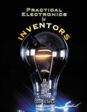
A comprehensive, project-oriented reference that ties together everything from passive components to microcontrollers — ideal as a capstone design companion.
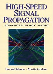
For the reader ready to go beyond ideal circuits, this book tackles real-world signal integrity, transmission lines, and the physical limits of fast digital and analog design.
Discussion
Keep reading
Paths that share books, cover the same subject, or open a related topic.