Get into robotics: build your first robot
This curriculum takes a complete beginner from zero to a working robot build across four progressive stages. It starts with the electronics and mechanical intuition every roboticist needs, layers in sensing and control theory, moves into hands-on programming and microcontroller work, and finishes with an integrated, project-driven capstone that ties every skill together into a real machine.
Foundations: Electronics & Mechanics
BeginnerUnderstand how electricity, circuits, and basic mechanical systems work — the physical bedrock every robot is built on.
▸ Study plan for this stage
Pace: 8–10 weeks, ~25–35 pages/day, 5 days/week — prioritize Chapters 1–6 (theory) in the first 4 weeks, then Chapters 7–17 (components & circuits) over the remaining weeks, with one weekend review session per chapter block
- Voltage, current, and resistance — and how Ohm's Law ties them together
- Series vs. parallel circuits and how to analyze them using Kirchhoff's Voltage and Current Laws
- Power dissipation and how to size components (especially resistors) safely
- Capacitors and inductors: how they store energy and behave in DC vs. AC circuits
- Diodes and transistors as fundamental switching and amplification devices
- Reading and interpreting schematic diagrams accurately
- Sensors and actuators as the bridge between electronics and the physical/mechanical world
- Basic signal types: analog vs. digital, and how real-world signals are conditioned for use
- Given a simple circuit with a battery, two resistors in series, and one in parallel, can you calculate the voltage drop and current through each component?
- What is the difference between a NPN and PNP transistor, and in what scenario would you use each as a switch?
- How does a capacitor behave the moment power is applied to a circuit, and how does that change over time?
- Why does power dissipation matter when selecting a resistor, and how do you calculate whether a resistor will overheat?
- What does a schematic symbol for a MOSFET look like, and how does it differ functionally from a BJT?
- How would you use a voltage divider to bring a 5V sensor signal down to a safe 3.3V level for a microcontroller?
- **Breadboard Ohm's Law lab:** Wire up at least five different resistor combinations (series, parallel, mixed) with a 9V battery, measure voltage and current with a multimeter, and compare your measurements to your hand-calculated predictions from Scherz's formulas.
- **Component identification drill:** Pull 20 random components from a starter kit (resistors, capacitors, diodes, transistors), identify each by markings or color code, look up its datasheet, and record its key ratings — mirroring the component reference tables in Practical Electronics for Inventors.
- **Transistor switch circuit:** Build a BJT (NPN) transistor circuit that uses a small control current (e.g., from a pushbutton) to switch a higher-current LED or small motor on and off — directly applying the switching concepts from Scherz's transistor chapters.
- **Schematic-to-breadboard translation:** Find three schematics from the book's worked examples, build each one on a breadboard exactly as drawn, verify they behave as predicted, then deliberately introduce one fault into each and practice diagnosing it.
- **RC timing circuit:** Build a simple RC (resistor-capacitor) charging circuit, use a multimeter or oscilloscope to observe the capacitor voltage over time, and verify the time constant τ = RC matches Scherz's formula — building intuition for how capacitors behave in robot power and signal circuits.
- **Design a motor driver concept:** Using only the theory from Practical Electronics for Inventors, sketch (on paper) an H-bridge motor driver circuit using four transistors, label every component with its role, and write a short paragraph explaining how reversing the control signals reverses motor direction.
Next up: Mastering how electricity flows through components and how mechanical forces are controlled by actuators gives you the essential vocabulary to understand how a microcontroller — the "brain" of a robot — reads sensors and commands motors, which is exactly what the next stage on embedded systems and microcontrollers builds upon.
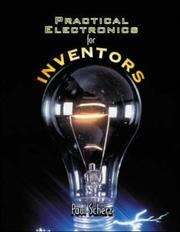
The single most comprehensive beginner-to-intermediate electronics reference: covers voltage, current, components, motors, and sensors in plain language. Reading this first gives you the vocabulary to understand every circuit you will later build.
Microcontrollers & Physical Computing
BeginnerLearn to program a microcontroller (Arduino), read sensors, and drive actuators — turning electronic knowledge into interactive, responsive hardware.
▸ Study plan for this stage
Pace: 6–8 weeks total. Week 1–2: Read "Getting Started with Arduino" cover to cover (~20–25 pages/day, ~150 pages); it is short and concept-dense, so re-read key chapters on digital/analog I/O and the IDE. Weeks 3–8: Work through "Arduino Cookbook" (~30–40 pages/day, ~700 pages), treating it as a hands-on
- The Arduino hardware ecosystem: board anatomy (pins, power rails, ATmega microcontroller), the IDE, and the sketch lifecycle (setup() / loop())
- Digital I/O: writing HIGH/LOW to output pins (LEDs, relays) and reading digital input (buttons, switches) with pinMode(), digitalWrite(), and digitalRead()
- Analog I/O: reading variable voltages from sensors with analogRead() (0–1023 ADC range) and producing pseudo-analog output with analogWrite() PWM for dimming and motor speed control
- Serial communication: using Serial.begin() / Serial.print() to debug sketches and exchange data with a host computer — the primary debugging lifeline for beginners
- Timing and control flow: using delay(), millis() for non-blocking timing, and structuring responsive programs that avoid freezing the loop
- Sensors and transducers: connecting and interpreting common sensors (potentiometers, LDRs, temperature sensors, ultrasonic distance sensors) as covered in the Arduino Cookbook recipes
- Actuators: driving LEDs, buzzers, servo motors, and DC motors (via transistors or motor shields) — translating digital logic into physical motion and sound
- Libraries and modularity: installing and using Arduino libraries (e.g., Servo.h, Wire.h) to abstract hardware complexity, as demonstrated throughout the Arduino Cookbook
- What is the difference between a digital and an analog pin on an Arduino, and when would you use analogRead() vs. digitalRead() — as explained in Getting Started with Arduino?
- How does PWM (analogWrite) simulate an analog output, and what physical effects does it produce on an LED or motor?
- Why is using millis() preferred over delay() for timing in interactive sketches, and how does the Arduino Cookbook demonstrate this pattern?
- How do you wire and read a pushbutton with a pull-down resistor, and what problem does the resistor solve?
- What steps does the Arduino Cookbook prescribe for connecting and calibrating a servo motor, and how does the Servo library simplify this?
- How would you use Serial.print() to diagnose a sensor that is returning unexpected values?
- 'Blink to Heartbeat' progression: Start with the classic Blink sketch from Getting Started with Arduino, then modify it to produce a double-pulse heartbeat pattern using millis() instead of delay() — proving you can write non-blocking timing logic.
- Analog dashboard: Wire a potentiometer and an LDR to analog pins; read both with analogRead() and print formatted values to the Serial Monitor every 500 ms. Map the potentiometer value to LED brightness via analogWrite() and observe the relationship between ADC counts and physical light output.
- Button-debounced state machine: Build a circuit with two pushbuttons and three LEDs. Use the debounce recipe from the Arduino Cookbook to cycle through LED patterns only on clean button edges — reinforcing digital input, debouncing, and simple state machines.
- Servo sweep controller: Following the servo recipes in the Arduino Cookbook, wire a hobby servo and write a sketch that sweeps it to an angle proportional to a potentiometer reading. Add Serial output showing the mapped angle, then constrain the range to avoid mechanical stops.
- Distance alarm: Connect an HC-SR04 ultrasonic sensor using the Arduino Cookbook's distance-sensing recipe. Drive a passive buzzer at a frequency inversely proportional to distance (closer = faster beeps), combining analogWrite/tone(), timing logic, and sensor reading in one integrated project.
- Mini-capstone — 'Responsive Nightlight': Combine an LDR (ambient light sensor), a pushbutton (manual override), and an RGB LED. The light should auto-dim in bright conditions, brighten in darkness, and toggle on/off with the button. Document the circuit with a hand-drawn schematic and annotate every function in the sketch — simulating real project documentation habits.
Next up: Mastering Arduino's sensor-to-actuator loop and serial communication establishes the physical computing intuition needed to tackle more complex robotic systems — where multiple sensors must be fused, actuators must be coordinated, and the microcontroller becomes just one node in a larger mechanical and computational architecture.
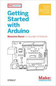
Written by Arduino's co-creator, this short book establishes the Arduino workflow and mindset quickly — the right starting point before tackling longer projects.

A recipe-style reference covering motors, servos, sensors, and communication — exactly the building blocks of a robot. Reading it after Banzi lets you look up and implement specific subsystems as you design your build.
Robotics Principles: Sensing, Motion & Control
IntermediateUnderstand how robots perceive their environment, how feedback control keeps them on track, and how mechanics and electronics combine into a coherent system.
▸ Study plan for this stage
Pace: 8–10 weeks total. Weeks 1–6: "Introduction to Robotics" by Craig (~25–30 pages/day, focusing on one chapter per sitting); Weeks 7–10: "Robot Building for Beginners" by Cook (~20–25 pages/day, pausing frequently to source components and attempt builds). Aim for 5 reading days per week, leaving weeken
- Spatial descriptions and transformations: how Craig uses homogeneous transformation matrices to represent a robot's position and orientation in 3D space
- Forward and inverse kinematics: computing end-effector pose from joint angles (forward) and solving for joint angles given a desired pose (inverse) as developed in Craig's kinematic chapters
- Jacobians and velocity kinematics: relating joint-space velocities to Cartesian-space velocities, and understanding singularities where control breaks down
- Dynamics and Newton-Euler / Lagrangian formulations: how forces and torques propagate through a robot's links, as covered in Craig's dynamics chapters
- Feedback control fundamentals: PID control loops, error signals, and how Craig frames position and force control to keep a robot on its desired trajectory
- Sensors and actuators in practice: Cook's hands-on treatment of motors (DC, servo, stepper), encoders, bump sensors, IR sensors, and how each translates physical phenomena into signals a microcontroller can use
- Circuit integration and power management: Cook's guidance on reading schematics, breadboarding, selecting motor drivers, and safely powering a mobile robot platform
- System-level thinking: bridging Craig's mathematical models with Cook's physical construction — understanding that every theoretical DOF and control loop must map to a real motor, sensor, and wire
- Given a 2-DOF planar robot arm with known link lengths, can you derive the forward kinematics using Craig's DH parameter convention and compute the end-effector position for a specific set of joint angles?
- What is the geometric or algebraic approach Craig presents for solving inverse kinematics, and under what conditions does a solution fail to exist or become non-unique?
- How does a Jacobian matrix connect joint velocities to end-effector velocities, and what physical situation does a kinematic singularity represent?
- Using Craig's control framework, how does a PID controller reduce steady-state error in a joint-position control loop, and what happens when gains are poorly tuned?
- From Cook's book, what are the trade-offs between DC motors, servo motors, and stepper motors for a beginner mobile robot, and how does each type require different drive circuitry?
- How do the sensors Cook describes (bump switches, IR proximity, encoders) feed back into a simple control loop, and how does this physical reality connect to the abstract feedback diagrams in Craig?
- DH Parameter Table & FK Solver: Choose a 3-DOF robot arm (real or drawn). Assign DH parameters following Craig's convention, build the transformation matrices by hand, then verify with a simple Python/MATLAB script that computes the end-effector pose for at least five joint-angle configurations.
- Inverse Kinematics Workspace Mapping: For the same 3-DOF arm, write a script that sweeps through reachable end-effector positions and plots the robot's workspace boundary, highlighting regions where the inverse kinematics has two solutions versus one, and where singularities occur.
- PID Tuning Simulation: Implement a simulated single-joint PID position controller (in Python or MATLAB/Simulink). Deliberately mis-tune Kp, Ki, and Kd one at a time, record the step-response plots, and write a one-page analysis connecting your observations to Craig's stability discussion.
- Breadboard Motor Driver Circuit (Cook-inspired): Following Cook's schematic guidance, wire an L298N or similar H-bridge to a small DC motor on a breadboard, control direction and speed via PWM from an Arduino, and measure current draw at stall vs. free-run to understand power budgeting.
- Sensor Integration Lab: Attach an IR proximity sensor and a rotary encoder to your breadboard setup (or a simple wheeled chassis). Write firmware that uses encoder ticks to estimate distance traveled and uses the IR sensor to trigger a stop — directly practicing the sense-plan-act loop Cook describes.
- System Integration Journal: As you finish both books, maintain a two-column journal: left column records a theoretical concept from Craig (e.g., a control law or kinematic equation); right column records the physical component or wiring decision from Cook that implements it. Aim for at least 10 paired entries to make the theory-to-hardware connection explicit.
Next up: Mastering Craig's kinematic and control mathematics alongside Cook's physical build experience gives you the vocabulary and intuition needed to tackle more advanced topics — such as motion planning, simultaneous localization and mapping (SLAM), and autonomous decision-making — where robots must reason about and navigate complex, real-world environments.
The classic university text on robot kinematics and control — reading it now, after you have electronics and programming basics, makes the math approachable and directly applicable to your own build.
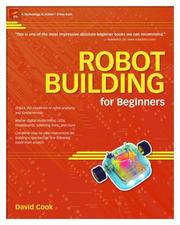
Bridges theory and practice by walking through every subsystem of a real autonomous robot: chassis, drive train, sensors, and logic. It reinforces Craig's concepts with concrete, buildable examples.
Capstone: Building & Programming Your First Robot
IntermediateIntegrate everything — parts selection, assembly, wiring, and software — to take a robot from a pile of components to a fully working, autonomous machine.
▸ Study plan for this stage
Pace: 6–8 weeks, ~25–35 pages/day; treat each chapter of "Programming Robots with ROS" as a self-contained sprint — read, then immediately implement the code/commands on a real or simulated robot before moving on
- ROS architecture fundamentals: nodes, topics, messages, services, and the master
- Building and managing a ROS workspace with catkin — package creation, CMakeLists.txt, and package.xml
- Publisher/Subscriber communication pattern and writing your first Python/C++ ROS nodes
- Robot description with URDF and visualizing your robot model in RViz
- Sensor integration — reading data from cameras, LiDAR, and other peripherals via ROS drivers
- Navigation stack setup: costmaps, move_base, AMCL localization, and path planning
- Manipulation and arm control using MoveIt! — motion planning, collision checking, and executing trajectories
- Simulation with Gazebo — spawning robots, adding sensors, and testing autonomy safely before deploying to hardware
- What is the role of the ROS master, and what happens to a running system if it goes down?
- How do you create a new catkin package with the correct dependencies, and what files must you edit to add a custom message type?
- Explain the difference between a ROS topic (pub/sub) and a ROS service (request/reply) — when would you choose each for a robot behavior?
- Walk through every step required to get the ROS navigation stack running on a new robot: what parameters must be tuned and why?
- How does URDF describe a robot's kinematic chain, and how does that description feed into both RViz visualization and MoveIt! motion planning?
- What is the workflow for testing a new autonomous behavior safely — from Gazebo simulation through to real-hardware deployment — as demonstrated in the book?
- Environment setup sprint: Install ROS on Ubuntu, create a catkin workspace, and write a 'Hello Robot' publisher node and matching subscriber node in both Python and C++ — verify communication with rostopic echo and rqt_graph.
- URDF build challenge: Model a simple two-wheeled differential-drive robot from scratch in URDF, add a simulated LiDAR link, load it into RViz, and confirm all transforms are correct in the TF tree.
- Gazebo autonomy loop: Spawn your URDF robot in a Gazebo world, attach a simulated laser scanner, run gmapping to build a map of the environment, then use the navigation stack (move_base + AMCL) to command the robot to three waypoints autonomously.
- Custom behavior node: Write a ROS node that subscribes to /scan (laser data), detects an obstacle closer than 0.5 m, and publishes a Twist message to /cmd_vel to stop and turn — test it first in Gazebo, then on physical hardware if available.
- MoveIt! arm exercise: Using the MoveIt! Setup Assistant, configure a simulated 4-DOF arm URDF, generate a MoveIt! package, and write a Python script using the MoveGroupCommander API to plan and execute a pick-and-place motion to predefined poses.
- Full-stack integration project: Combine everything — bring up your robot (real or simulated), run the navigation stack, and write a mission-control node that autonomously visits a sequence of map waypoints, logs sensor data to a ROS bag, then plays the bag back for offline analysis.
Next up: Completing this capstone gives the reader a fully operational ROS-based robot and hands-on fluency with the entire software stack, providing the practical foundation needed to tackle advanced topics such as multi-robot coordination, deep-learning perception pipelines, or custom hardware design in subsequent stages.

ROS is the industry-standard robot operating system; this book introduces it at a practical level so your robot's software architecture is professional and extensible from day one.
Discussion
Keep reading
Paths that share books, cover the same subject, or open a related topic.